Messing Around With VoIP (my portfolio submission)
November 2023 (3407 Words, 19 Minutes)
3CX Self-Hosted PBX
Applied Early Action to MIT and Early Decision to Columbia University with this project and write-up (2023-2024 application cycle).
1. The Goal
Initially, this started off as a way to explore a topic that was glossed over in my CCNA studies, only being mentioned once or twice in the entire curriculum. There was too much expanse in VoIP for my curiosity to not be tapped in. How do business phone systems work? Whenever we call customer service, how do they transfer us to a representative? Why do companies have an automated bot before they can refer us to the right department or human? Luckily, we can explore these and more with a PBX (private branch exchange) system right on a Raspberry Pi. I’ll get to some of the potential applications of this system near the end, but the crux is that this was an exploration of how a business would deploy a PBX and what we can do with it.
2. Deciding on 3CX
Before I even thought about what I’d do with a PBX, I first set my mind onto figuring out what solution to use and how I’d set it up. 3CX was the clear winner for my case: it was self-hostable, had a version specifically for Raspbian (the Raspberry Pi operating system), and supported my old (but gold) Cisco 7821 phone. This is what the interface looks like after an install:
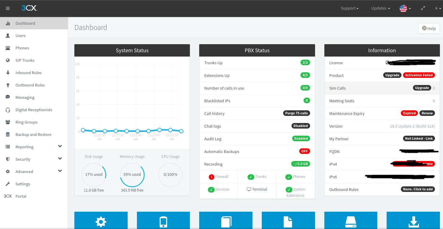
Figure 2.1: the 3CX interface as it appears for me
What’s also gravitating about 3CX is that it has a mobile app for softphones (such as iPhones and Androids), making it possible to take the PBX experience on the go. Even if I (or a small business) didn’t have an IP phone, it’d still be worthwhile to set up in order to tie all their mobiles together.
3. Onboarding Devices
To even use a PBX, I needed devices to link it to. Depending on which type of device is to be set up, the provisioning process wildly differs.
Softphones
Since many mobile phones (iPhones and Androids of all kinds) are not solely dedicated to voice telephony, they are referred to as softphones. Their onboarding is deceptively simple with 3CX: a QR code is generated, and you scan it with your mobile, automatically registering your device with the PBX:
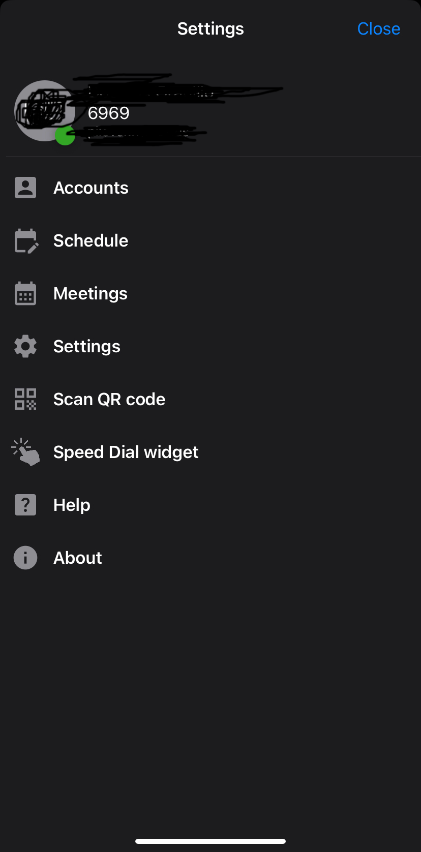
Figure 3.1: appearance of my 3CX iOS app’s settings menu after onboarding
The IP Phone
For my Cisco 7821, it’s a dedicated device for placing and receiving calls, marking it as an IP phone (I call it a hardphone, personally). The setup is a lot more involved for these types of phones, requiring some tinkering with DHCP options in order for them to automatically pick up their configuration. In my case, I needed to have my phone able to register with 3CX at all. Since it’s Cisco, there’s tie-in with their custom call control software (Unified Communications Manager) at the firmware level. Hence, I needed to unlock it for open subscription with any call control software (known as third-party call control, or 3PCC). After obtaining a product activation key (assigned by MAC address) for the 3PCC firmware through Cisco’s licensing portal, I was able to download the license file required to install it.
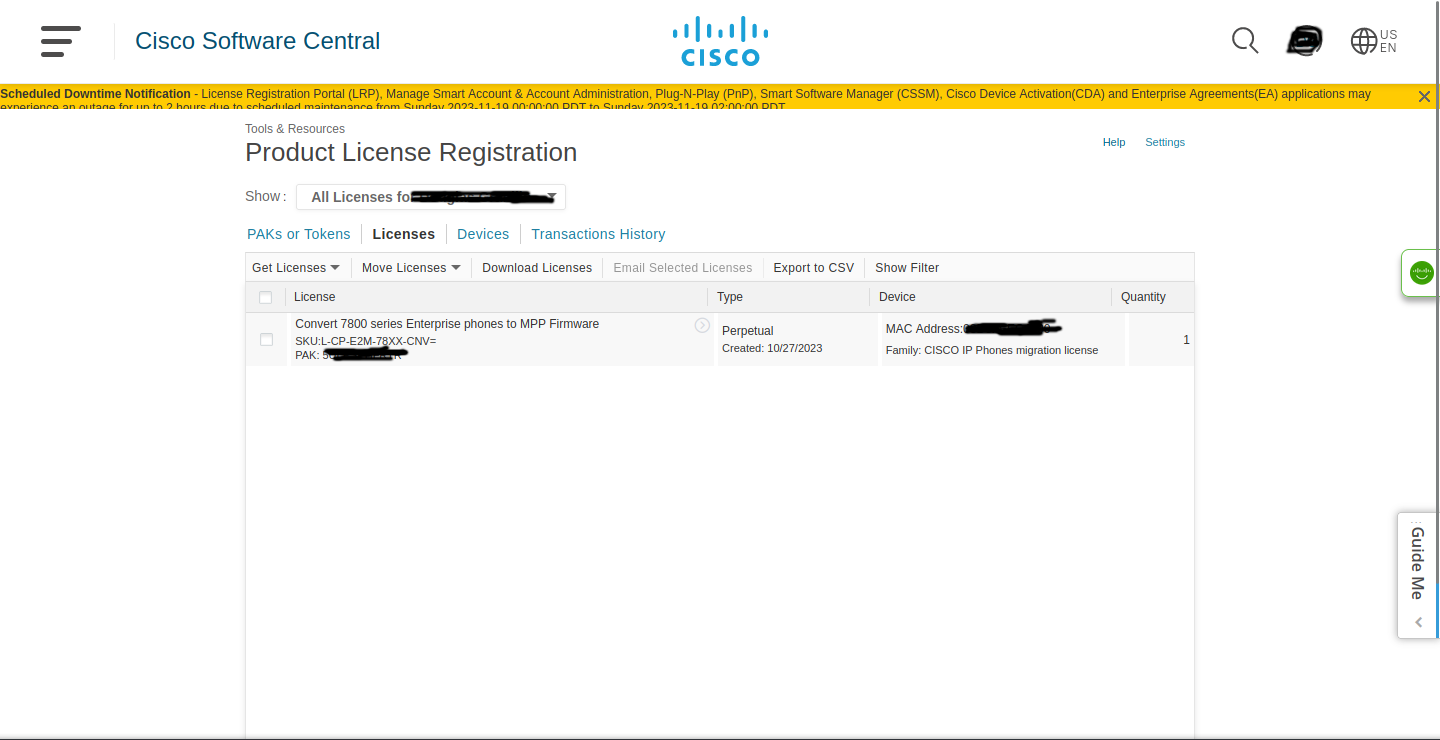
Figure 3.3: The Cisco License Registration Portal, with my PAK associated with the phone
But to have the phone connect to the internet and download the firmware, I needed to instruct it to fetch the necessary files. This is where those DHCP options come into play.
Little problem, though: my home router doesn’t support setting these options. It is a consumer router, without much ability to granularly control configurations such as the aforementioned DHCP options.
The solution was using my own Cisco 1841 router in combination with a Cisco Catalyst 2960 switch to connect it to my lab network. I already had these from my CCNA studies to practice with real hardware (software emulation just feels too fake for me), but now it was time to employ them in a real-world scenario.
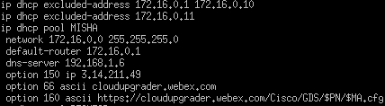
Figure 3.4: A fragment of configuration on my Cisco router
Alongside defining a private network (172.16.0.0/24), I’m distributing my router’s IP address, the DNS server (hosted on the same Raspberry Pi on my local network), and the required options to clients:
- 150: Cisco’s TFTP server, where the firmware will be downloaded from.
- 66: The hostname of the server from where the configuration will be downloaded.
- 160: The full link to the phone’s configuration, with
$PNand$MAas variable names which the phone can fill in.
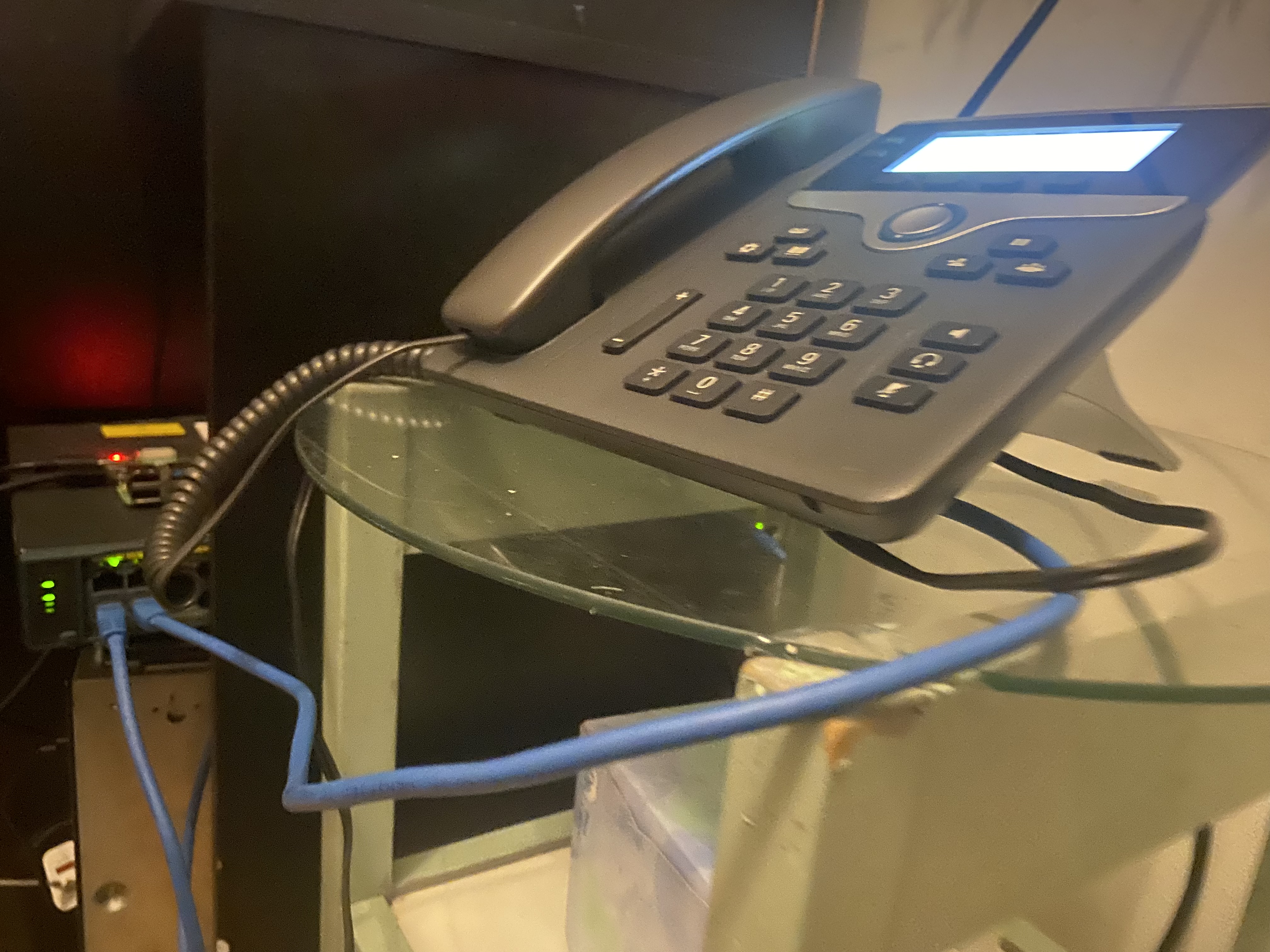
Figure 3.5: My Cisco 7821 connected to my switch, with my Raspberry Pi lying on top
After connecting my phone to the internal network after configuration though, it wasn’t able to download the firmware or reach the external servers specified in the options. Connecting my computer to the switch, it was no different. I couldn’t visit any websites or access anything outside of my internal Cisco network.
4. NAT the Problem
Upon realizing the network access problem, I immediately attempted to slash off any immediate issues. I checked that my Cisco router was connected to my home router, and it was. If something isn’t connected, nothing can happen. I went up the OSI model to Layer 2 issues; namely, if my devices could even reach my Cisco router. No routing can happen without a clean link to it, so I tested reachability with the ping utility.
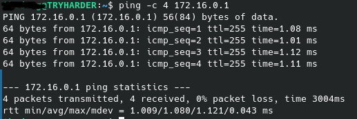
Figure 4.1: The ping command on Linux, being used to deliver four ICMP echo requests to the Cisco router
My internal router gave responses for each echo request, so reachability to it wasn’t an issue.
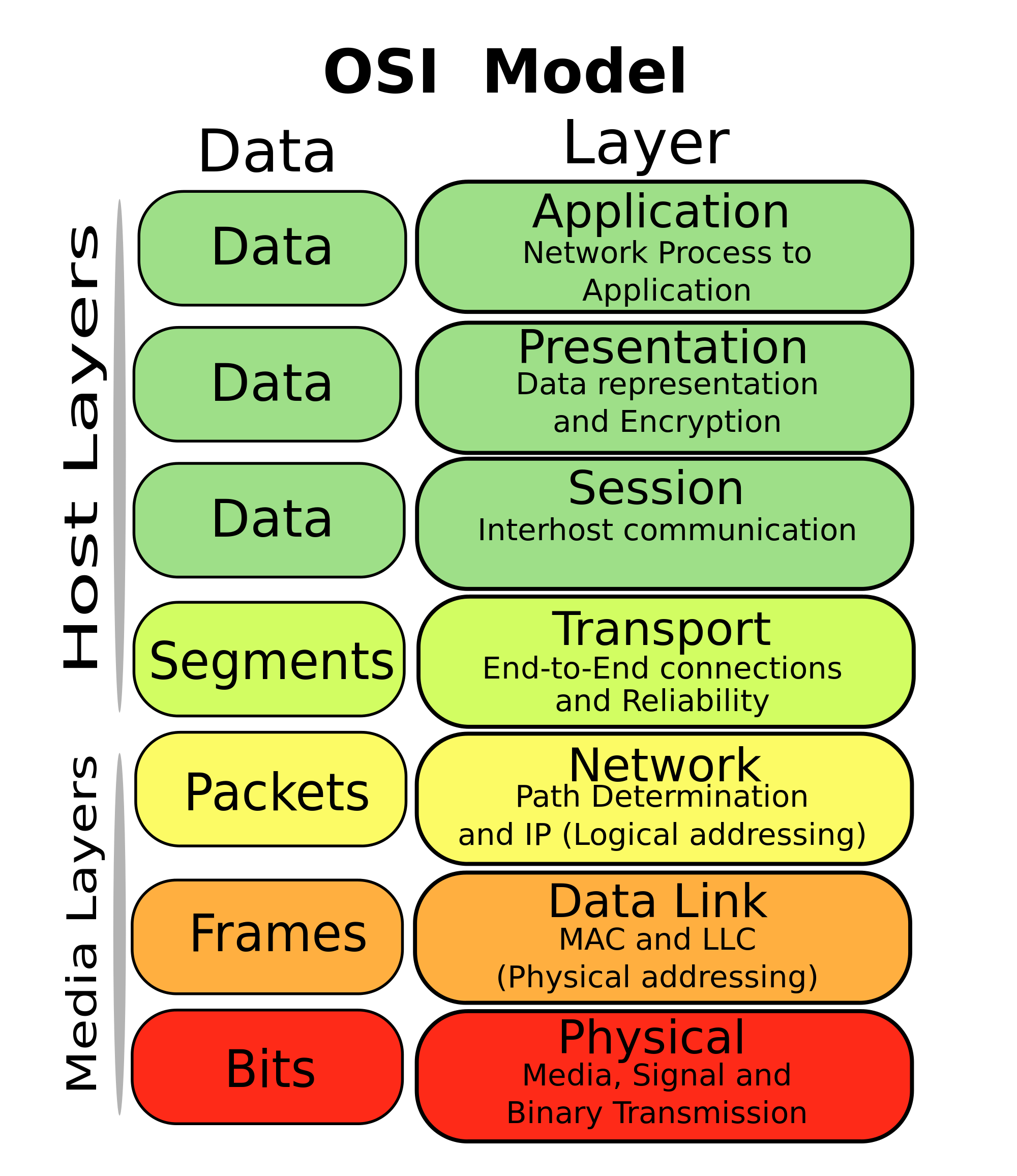
Figure 4.2: The OSI model
Traveling up the OSI model, the network layer was my next target. It was entirely possible that my Cisco router didn’t know how to reach external websites; thus, it dropped any traffic destined for them.
Attempted Solution #1: A Default Route
Setting a default route would allow the router, if the address wasn’t immediately in its routing table, to send it to a destination that may know where to send the traffic.
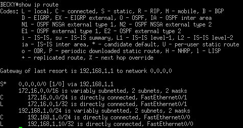
Figure 4.3: My Cisco router’s routing table, with the default route included
An example: If my computer needed a hostname resolved (google.com for reference), it contacts its DNS server (9.9.9.9 for reference). As depicted, my Cisco router doesn’t have 9.9.9.9 in its immediate vicinity, so the DNS request is sent to my Optimum router. The request is then sent to the public internet, eventually reaching Quad9’s server and returning a DNS response.
Sadly, I still can’t access websites, even with this default route set. At this point, I realized that I may have been moving too fast in my problem solving process. I hadn’t checked reachability to the router yet. Promptly, the issue was here: my home router didn’t return a single ICMP echo to my workstation.
Attempted Solution #2: Network Address Translation
Before thinking about any solutions to the connectivity problem, I graphed the problem out.
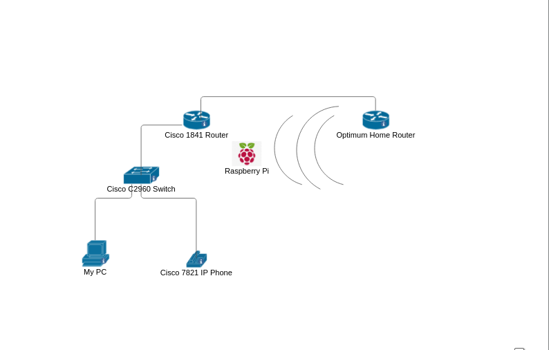
Figure 4.4: A diagram of my devices in both networks
Logically, my packet is routed to the home router, since the Cisco router has a path there. Thinking about it graphically, there shouldn’t be any problem with traffic getting to the Optimum router (there’s an entry to the 192.168.1.0/24 subnet in the routing table). At this point, I’ve narrowed the issue down to the home router. It can’t send a reply back to my workstation, which is where everything falls apart.
Note: my Raspberry Pi is now connected wirelessly to my home router because I ran out of Ethernet cables and needed to move my setup around a bit.
Glancing at the graph, it’s one of two afflictions. Either the Optimum router isn’t sending traffic back or my Cisco router isn’t. To figure out which, I reflected on IP packets and routing tables.

Figure 4.5: A Wireshark capture of an ICMP packet I sent to the Optimum router
For the packet to get anywhere outside the network, a router needs to route it to its destination. The reason that it arrives at the Optimum router is because the Cisco 1841 has an entry for the destination and where to send it. In network operations, the source IP never changes (unless using source NAT) until the packet reaches its destination (the source and destination IP addresses are swapped here).
The predicament lies here. When the home router needs to send the packet back, it has no entry to the 172.16.0.0/24 subnet, forcing it to drop the packet. For me, this was a conundrum. Optimum doesn’t give the option to modify the routing table, and their customer support wasn’t much help. But that didn’t stop me from trying.
Is there a way to have the Cisco 1841 serve as a relay between internal devices and the home router?
A quick Google search of have router act as relay to public internet returned some Cisco documentation on NAT. The technology is most commonly employed to have multiple clients behind one router (how most home networks operate), and I could utilize it to solve my predicament too.
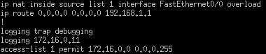
Figure 4.6: The NAT configuration on my Cisco router
FastEthernet0/0 is the interface connected to the home router, having an IP in the 192.168.1.0/24 subnet through DHCP. Hence, it can be used for NAT purposes. The configuration implements an access-list, often used for firewall configurations. Here, I used it to tell the router which source addresses to translate (in this case, every device behind the switch).
I added the overload keyword to the configuration because I had more than one device connected to my switch, and this permits the router to have one “public” address stand in for all of these devices’ outbound traffic. Now, the source IP should be modified to the one FastEthernet0/0 is assigned when packets are sent out to the Optimum router.
Ideally, it knows where the CIsco router is and sends a reply back to it. Through the use of TCP/UDP port numbers and other protocol identifiers, it should reverse the translation and guarantee safe passage of the packet back to my devices.
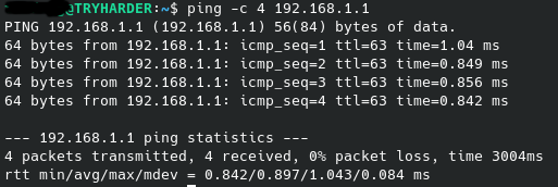
Figure 4.7: Successful ping test between my home router and PC
And score! NAT saves the day while letting me proceed with my phone setup. A restart later, it’s undergoing a firmware upgrade. 3CX, here we come.
5. Onboarding Devices (problem solved)
Without embargo, the firmware upgrade finishes and I can provision the phone with 3CX.
But then Problem #3 strikes: the provisioning link 3CX gives returns a 404 Not Found when it’s to be retrieved by the phone.
The link was to a file which was supposed to contain all of the necessary information to register the phone to the PBX. But we always have the option of punching it in manually! Specifically, I wanted the subscriber authentication details (not unlike how you connect to your cellular provider). Luckily, 3CX had them in plain sight for me to then punch into my phone’s web configuration utility.
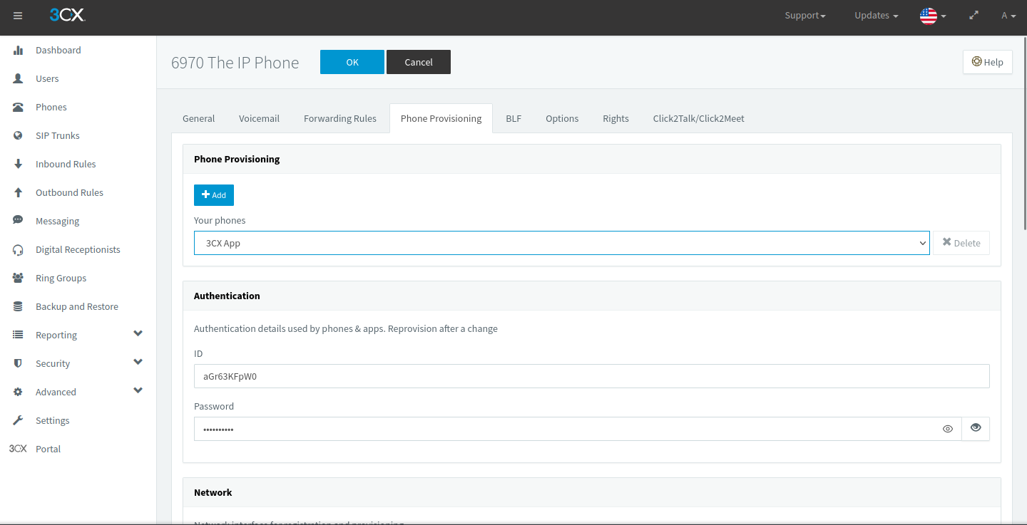
Figure 5.1: The Phone Provisioning menu in 3CX, with the authentication details visible
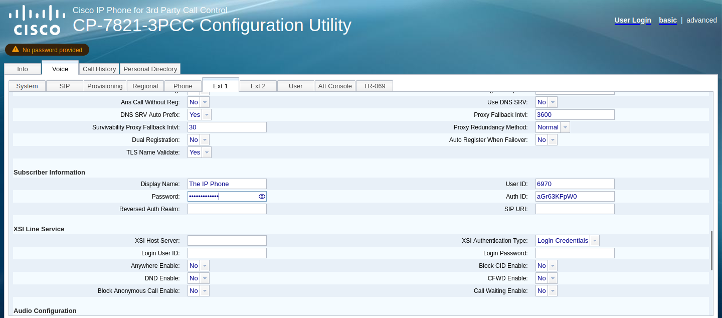
Figure 5.2: My Cisco 7821’s web configuration utility, with the entered subscriber information onscreen
A quick restart later, the phone registers with 3CX and is given the appropriate extension. It’s provisioned as a Cisco 7941, but their configuration files are incredibly similar. Hooray for backwards compatibility!
6. Using 3CX’s Basic Functionality
Internal Calls
The most basic feature of any PBX, I’m able to call other devices registered to it. This is true when they’re in my house or not! With the magic of port forwarding, I can have my 3CX instance publicly accessible on the internet, as to have devices be reachable from anywhere.
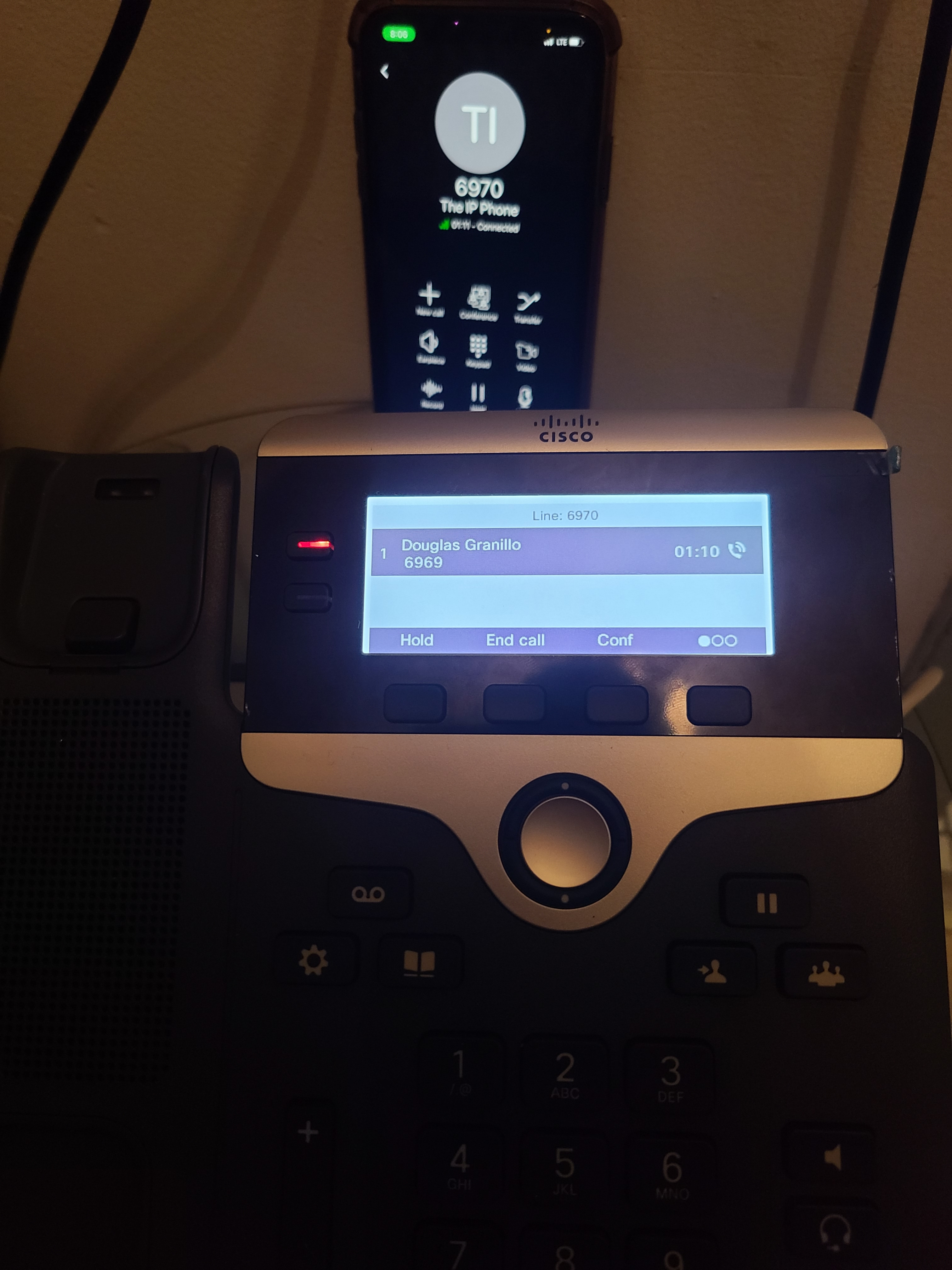
Figure 6.1: My cell phone (connected to LTE) and Cisco 7821 in a one-to-one call
The manner of operation in calls like this is worth exploring. When a call is to be established, SIP (Session Initiation Protocol) is used to prompt 3CX to ring the recipient through the use of an INVITE message. This is also why PBX servers are sometimes known as proxies in VoIP: they mediate the signaling and real-time audio of phone calls between multiple registered devices.
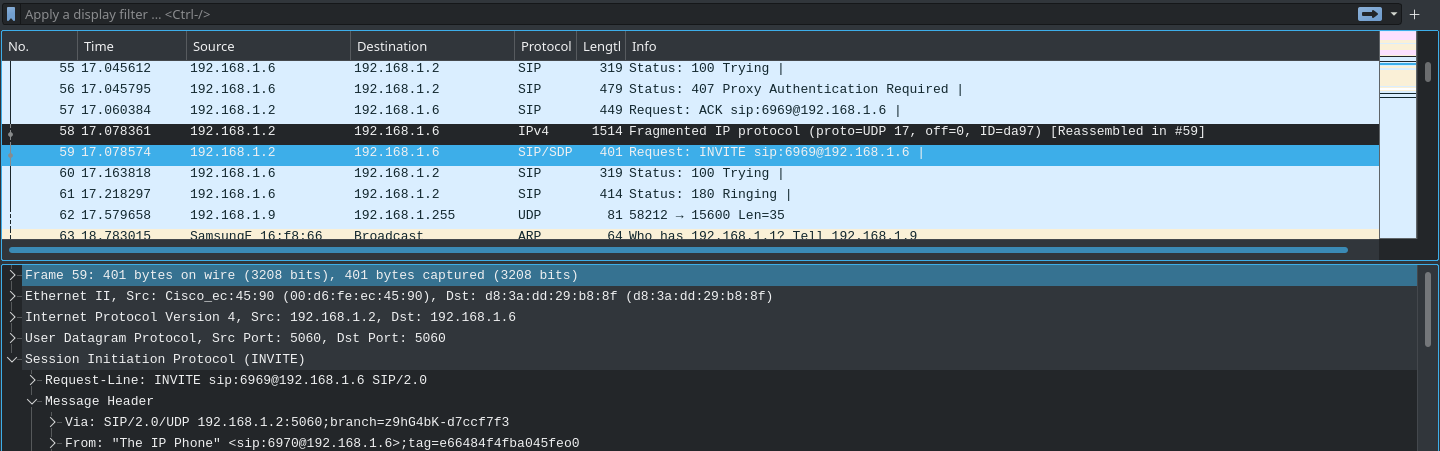
Figure 6.2: A Wireshark capture of a phone call between the two devices in the previous figure
Once the call is established, 3CX acts as a broker between the clients, processing the voice data and pushing it to the other devices on the call. The same goes for leaving the call; a BYE message is sent through SIP, notifying all other VoIP clients that they have left.
Conference Calls
Unlike many traditional VoIP clients, PBX clients allow for conference calls (multiple people on one call). PBX systems use “in-dialog” SIP INVITE messages with the tag of the client that started the conference to indicate when a conference is started, sending RTP streams to all clients that are part of the conference (except the sender).
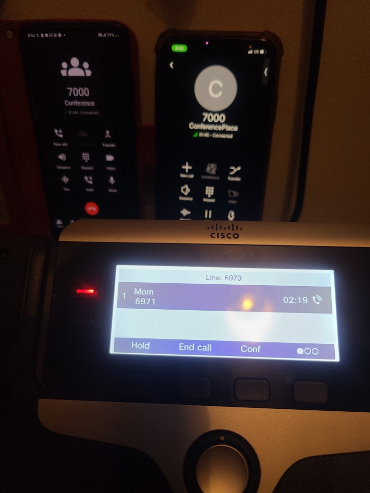
Figure 6.3: A conference call between multiple devices with 3CX
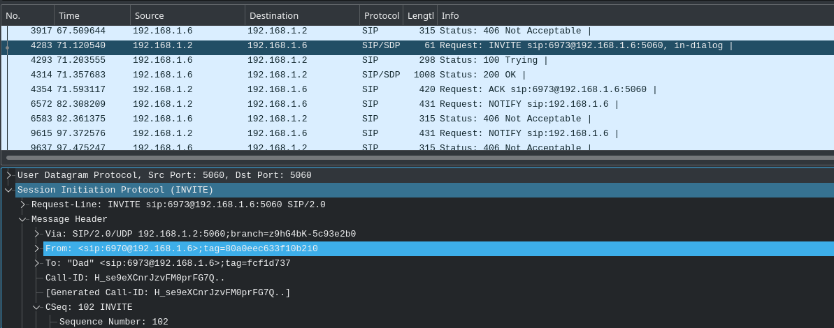
Figure 6.4: An in-dialog SIP message used for conference calls in a PBX
Transferring Calls
One of the PBX features most commonly used in customer service, these are used to refer a caller to another party, either internal or external to the PBX. The SIP REFER method is used for seamless transfer of the call without either side having to manually terminate the call; a BYE message is sent by the original recipient to the caller, since no further communication should occur between them.
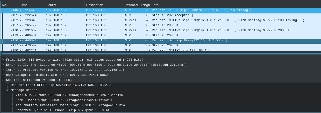
Figure 6.5: An in-dialog SIP REFER message and subsequent BYE message during call transfer
Putting a Caller on Hold
One of the most common features of consumer and enterprise VoIP clients, a hold is used to keep a call established without voice communication occurring. A preconfigured audio file may be played by the holder, but no other audio transmission is allowed. If you ever find yourself with a telemarketer on the line, it’ll quickly become your favorite VoIP feature, guaranteed.
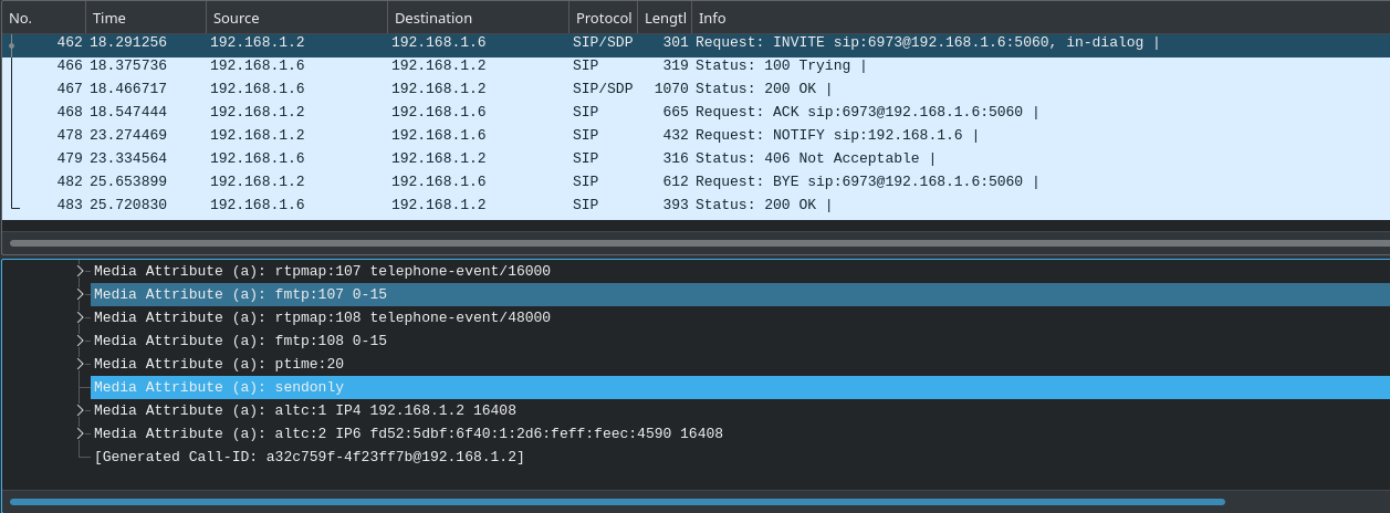
Figure 6.6: A re-INVITE SIP message sent to put a call on hold
The media attribute “sendonly” indicates that the call is to be put on hold, and “recvonly” being attached to the other client. In this fashion, neither side can both send and recieve RTP data, ensuring no verbal communication between both parties.
Voicemail
A feature nearly everyone’s used at some point! Voicemail uses an RTP audio stream demarcated by DTMF start and end signals and puts it in reserve on the PBX, allowing clients to access messages callers have left them while unavailable. In the case of 3CX, a PIN is required to access your personal voicemail, entered via a keypad. The way this works is worth delving into a bit, as it’s interesting and applies every time you make inputs via the keypad during a call.
DTMF (Dual-Tone Multi-Frequency) signals are not transmitted over the air as the numbers or symbols themselves, but as two audio cues at a specific frequency which are decoded by digital signal processing on the receiver’s end. These are sent as RTP event data, which correspond to the numbers typed on the dialpad. If these match up with the PIN recorded on the PBX, the caller is given access to their inbox.
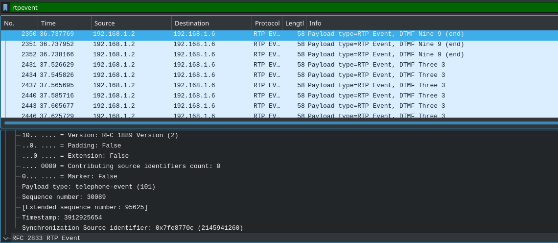
Figure 6.7: A voicemail PIN being transmitted as DTMF signals
7. Link to the Outside World
A PBX is an awesome thing to have for internal use, but it’s paramount to connect it to the public telephone network so others can dial into it too! This is how companies have public phone numbers you can call them by. I wanted to have my PBX be public (inbound only, outbound was too expensive) mostly for the fun of it, but also to try out the digital receptionist that many customer service call centers have. Practically though, if a user has limited calling on their cellular plan, a SIP trunk would be a cheaper way to take calls without using their minutes (only about $0.18 an hour). It does pose the question: what is a SIP trunk?
A SIP trunk bridges the public telephone network and privately hosted communications services such as PBXs. A phone number on the public network will be assigned to the client, used for reachability from devices using it. The PBX is connected to the SIP trunk provider, allowing calls to be forwarded to it. When the number is called, the provider forwards the SIP INVITE request (decrementing the Max Forwards SIP header value by 1) directly to the PBX, where it can respond accordingly.
I used a service called CallCentric for my SIP trunk provider, as they were the cheapest and easiest to set up (I got an entire 168 hours of talk for $5.00).
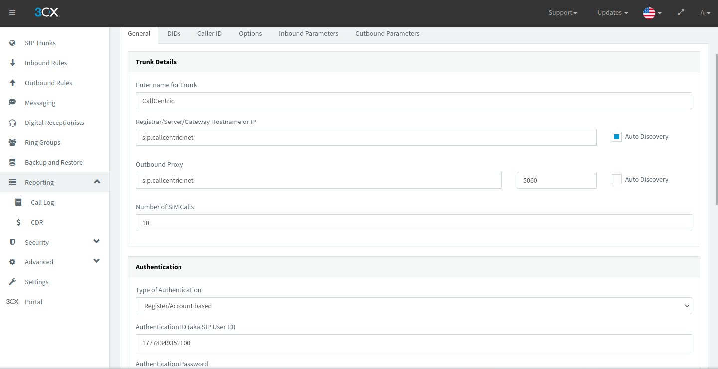
Figure 7.1: My SIP trunk provider linked to my 3CX instance
Since this is still using SIP, authentication is required to use the phone number assigned to you (don’t want random people taking calls meant for you now).
Once I got my public phone number set up, I directed calls made to the number to the digital receptionist I set up; it resembles many automated menu systems that you see in helpdesk or internal PBXs at large corporations. Prerecorded audio plays, often instructing the user on what to dial and telling them their available options.
I set mine up using DTMF signals as input, with inputs more than one character long able to be processed. For example, “1” could be for the manager and “13” for a CEO. “Connect to Extension” hands off control of the call to a client that has the extension in question; at the SIP level, it works just like a transfer. Personally, I used my menu to let me dial my family members in addition to a hidden option.
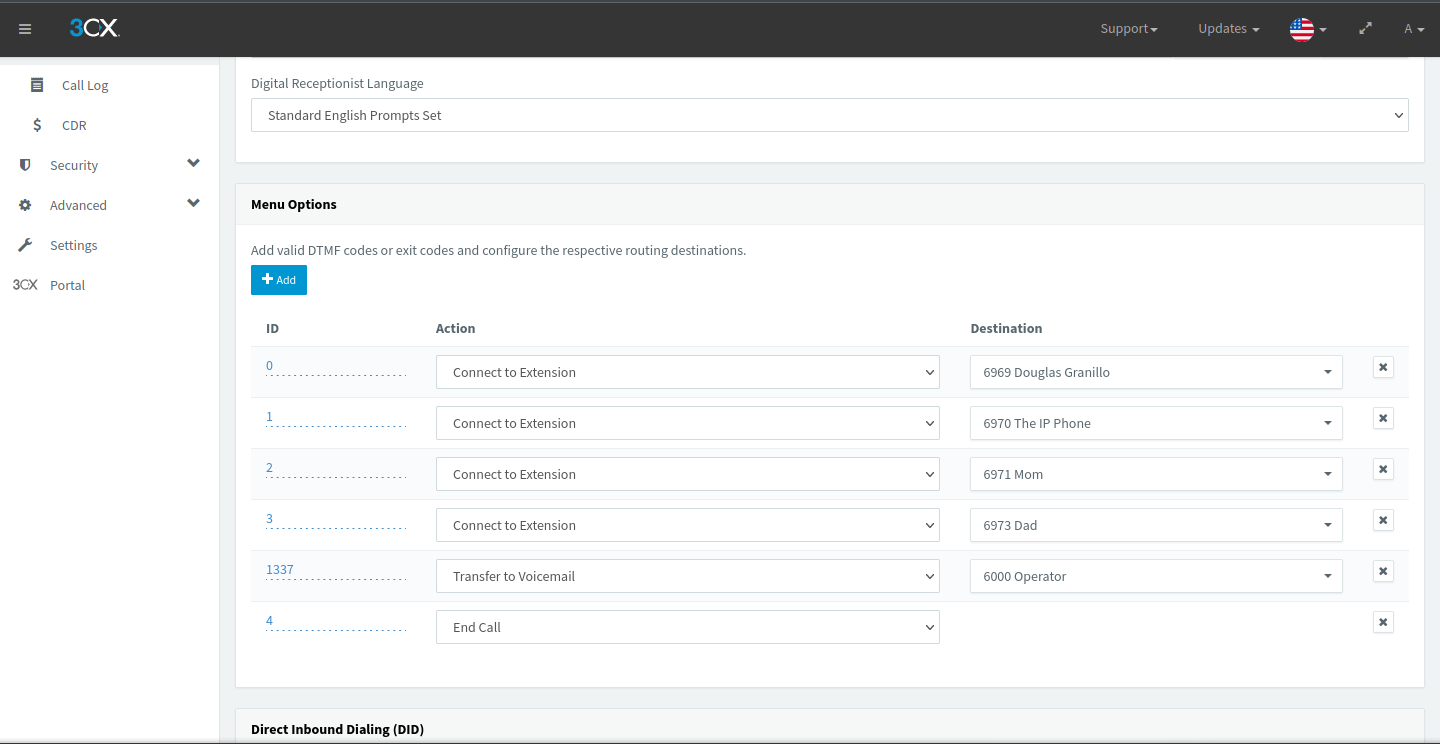
Figure 7.2: My digital receptionist’s (called Select Your Fighter) DTMF options in 3CX
Fun fact: The voicemail message for the Operator is the entirety of “White and Nerdy” by Weird Al, to mix in some nerdy fun with my calling.
Of course, having my PBX accessible to the public exposes me to scam callers and telemarketers. The “blacklisted numbers” feature of 3CX does exactly what it says: blacklist certain phone numbers from reaching your PBX.
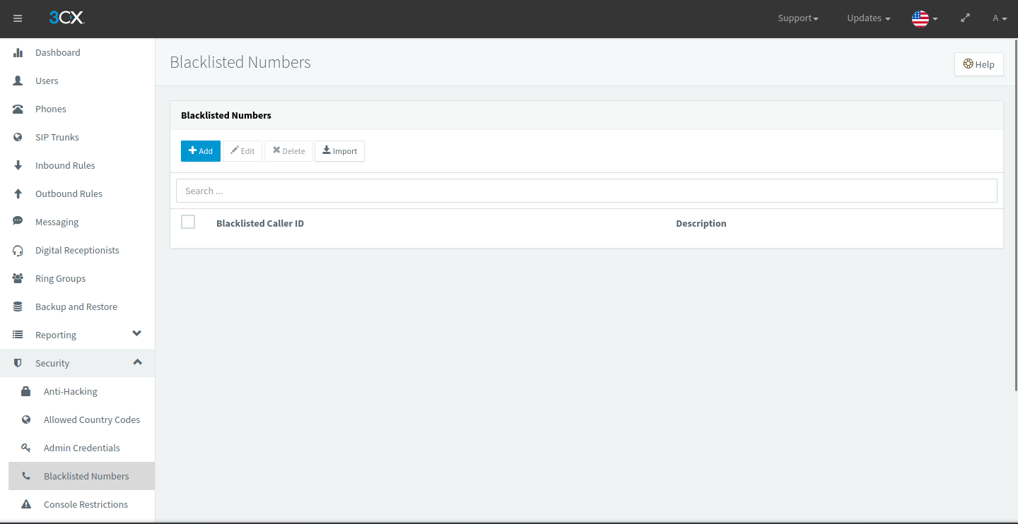
Figure 7.3: The blacklisted numbers list in 3CX (nothing here at the moment)
In SIP, blocking based on caller ID is indicated by response codes such as 603+ and 608, telling the caller that the recipient doesn’t want to be called by them.
8. Prioritization
If you think about it, voice traffic is heavy to transport on a link. It’s consistently taking up bandwidth during a call and needs to travel quickly so as not to decrease call quality for either side. Luckily for us, QoS is a way we can prioritize the voice data on the wire over other kinds of traffic.
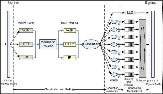
Figure 8.1: A detailed diagram of how QoS works
QoS is a complex set of software tools that can be used to optimize traffic flow and give special treatment to certain kinds of traffic during times of congestion.
- DSCP markings in the IP header indicate the priority that the packet should have in the queuing process.
- Congestion avoidance is used to drop packets randomly or based on priority class; it exists to prevent TCP global synchronization, where congestion and network underutilization will repeat in waves.
- Queuing groups packets of the same class together and sorts them based on when they will be transmitted out of the interface.
- Scheduling organizes the queues for transmission based on how much link bandwidth they have dedicated to them and on traffic class.
We can employ these to ensure that our calls are lag-free and clear, despite the bandwidth exhaustion there may be.
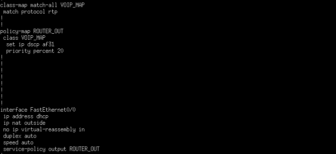
Figure 8.2: QoS configuration on my Cisco 1841 router for voice traffic
Here, I configured a “class map” (in Cisco’s terms) to identify which packets will be given special treatment by QoS. I’ve specified RTP as the protocol to be matched, as these hold the audio data of voice calls. If you’re wondering why SIP isn’t prioritized, it’s due to its function as a signaling protocol, with transmission of SIP packets much less frequent than RTP packets.
Next, I configured a “policy map” (again, in Cisco’s terms) to define what to do with these voice packets. I gave them a high percentage (20%) of link bandwidth during congestion because I do not want phone calls to become a slog for anyone on my network. In addition, I made it so voice packets would be marked with DSCP AF31, which is a high priority marking with a low drop probability.
Finally, I configured the policy map to be used outbound on the FastEthernet0/0 interface, ensuring that the router will route the audio with the DSCP marking I specified earlier.